Hey guys, this is very interesting design which you are going to observe now. Which makes use of magnetic force and create a rotatory motion exploiting the nature of reciprocating motion. And the most amazing nature of this design is, it uses a very low energy to harness a very large amount of energy, now its up to you to determine the hidden energy source to identify the extra energy and where it is coming from.
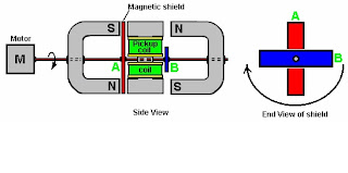
 This design consist of two horse shoe magnets, a magnetic shield which is usually a material with very low permeability or the magnetic lines of forces, some springs and a rotor and a electrical motor.
Working of the Machine :- Start from point A where the shaft is rotated mechanically or by an electric motor which passes through the NU metal sheets (both B). Let say one metal sheet is aligned at right angle to the other, than one rotation of shaft A produce two rotations of shaft D. Initially left B is covered by NU metal sheet whereas right B is perpendicular to magnet which attracts C towards itself and make shaft D forwards until the rotation is completed up to 90 degrees. For 90 to 180 degrees C is attracted by left magnet and this makes the backward motion of shaft D. This completes the one revolution of shaft D due to half rotation of shaft A. so one full rotation of shaft A will produce two full rotations of shaft D.
Springs of proper spring constants must be selected in order to produce proper reciprocating motion and control from attraction of magnet.
Main Points : We are producing rotation of shaft D by shaft A, than what is the point, we have motor to produce rotational enerty than why we are using this arrangement.

And there is one more design which can be used directly in order to generate electricity. Here a yoke is implemented on which the windings are done. Which directs the magnetic flux to flow properly through the coil and you know the yoke is assembly of identical iron strips which joined together and used rather than the whole iron alloy is used. This type of designing is used because it reduces eddy currents, whenever a changing magnetic flux passed through some conductor (closed loop) electricity is generated, similarly when an changing flux is passed through iron bar it induces current loops within bar and heat it up in the form of eddy current loss, this will loss the energy. So by lamination we induce a air gap in between the two bars and does not lead to formation of big loops and reduce eddy current by very big amounts.
If you have any queries and question regarding this model, feel free to ask me at hemant007manwani@gmail.com

Working of the Machine :- Start from point A where the shaft is rotated mechanically or by an electric motor which passes through the NU metal sheets (both B). Let say one metal sheet is aligned at right angle to the other, than one rotation of shaft A produce two rotations of shaft D. Initially left B is covered by NU metal sheet whereas right B is perpendicular to magnet which attracts C towards itself and make shaft D forwards until the rotation is completed up to 90 degrees. For 90 to 180 degrees C is attracted by left magnet and this makes the backward motion of shaft D. This completes the one revolution of shaft D due to half rotation of shaft A. so one full rotation of shaft A will produce two full rotations of shaft D.
Springs of proper spring constants must be selected in order to produce proper reciprocating motion and control from attraction of magnet.
Main Points : We are producing rotation of shaft D by shaft A, than what is the point, we have motor to produce rotational enerty than why we are using this arrangement.
- If the NU metal sheets used are very light, than the load on motor B will be very low and you can also use a simple 1.5 volt DC motor to run it.
- You are having a powerful force to rotate the rotor, which can be use to rotate higher loads.
- Where is the extra energy coming from, that is the main question, and the answer is hysteresis during the hysteresis cycle or the iron C, there is a loss of energy which is given by the hysteresis loop cycle curve.

And there is one more design which can be used directly in order to generate electricity. Here a yoke is implemented on which the windings are done. Which directs the magnetic flux to flow properly through the coil and you know the yoke is assembly of identical iron strips which joined together and used rather than the whole iron alloy is used. This type of designing is used because it reduces eddy currents, whenever a changing magnetic flux passed through some conductor (closed loop) electricity is generated, similarly when an changing flux is passed through iron bar it induces current loops within bar and heat it up in the form of eddy current loss, this will loss the energy. So by lamination we induce a air gap in between the two bars and does not lead to formation of big loops and reduce eddy current by very big amounts.

If you have any queries and question regarding this model, feel free to ask me at hemant007manwani@gmail.com